
GRP shaft
Computer-controlled filament-wound fiberglass shaft; dimensions and structural requirements are confirmed for the site.
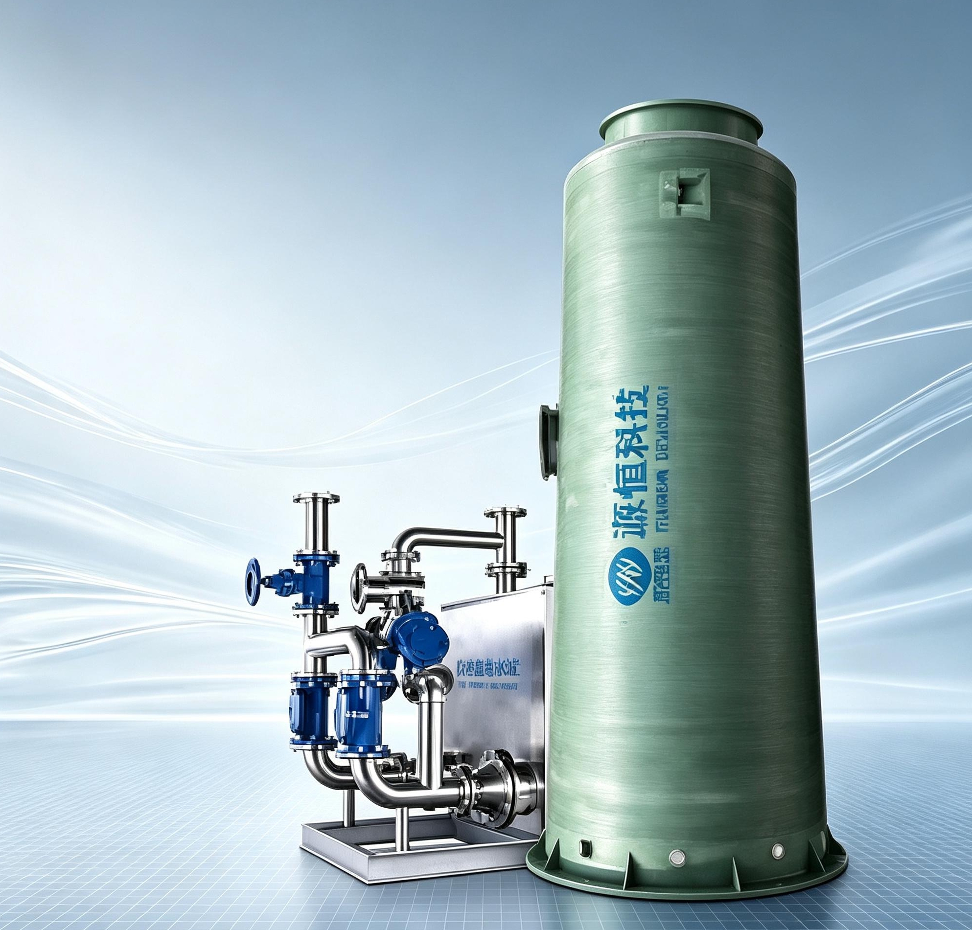
SEWAGE COLLECTION & LIFTING
A factory-integrated buried station that collects sewage or drainage and lifts it to a downstream sewer or treatment facility. The GRP shaft houses project-selected submersible sewage pumps, automatic couplings, internal pipework, level instruments, screening and controls.
Start with flow, inlet/outlet levels, medium and project location.
SYSTEM CUTAWAY
The submersible pumps sit inside the collection shaft. Liquid level initiates the pumping cycle and the discharge pipe conveys the flow to the receiving system.
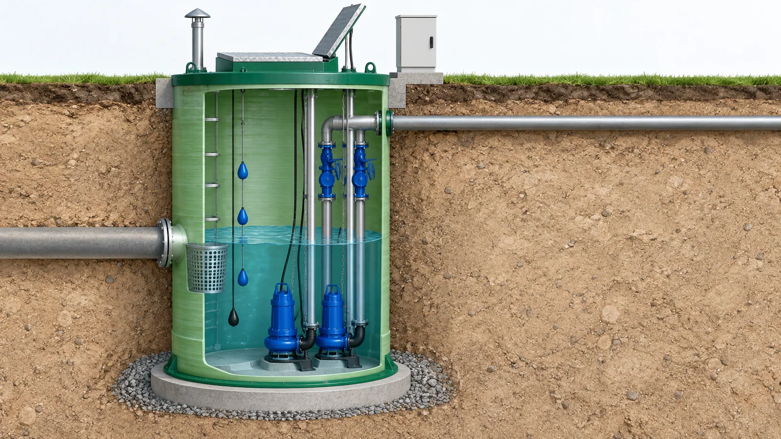
Sewage or rainwater enters the shaft and passes the selected screening arrangement.
Level instruments send start, stop and alarm signals to the control panel.
The selected duty pump starts when the operating level is reached.
The pump lifts flow through the internal riser and outlet pressure pipe.
Logic is configured for stop level, pump alternation, standby response and alarms.
01 / DEFINE THE DUTY POINT
Flow alone is not enough. Elevations, pipe losses, solids and site conditions determine the pumps, shaft and control arrangement.
| Design input | What to provide | What it determines |
|---|---|---|
| Design and peak flow | Average and peak inflow in m³/h, plus the operating pattern. | Pump duty point, quantity and effective storage volume |
| Head and levels | Inlet invert, discharge elevation, pipe route and receiving-main condition. | Static head, friction loss and total dynamic head |
| Pumped medium | Sewage, rainwater or drainage; temperature and known solids, fibres or grit. | Pump passage, impeller type and screening arrangement |
| Pipe interfaces | Inlet/outlet diameter, direction, material and connection requirements. | Shaft openings, internal pipework and valve selection |
| Site conditions | Burial depth, soil, groundwater, surface load and installation access. | Shaft dimensions, foundation and anti-flotation design inputs |
| Power and control | Voltage/frequency, duty/standby preference, alarms and monitoring needs. | Motor, panel, level control and optional remote functions |
No hydraulic calculation yet? Send the available pipe levels, route and expected flow. Unknown values can be marked “Please advise”.
02 / INTEGRATED COMPONENTS
Each component is confirmed in the equipment schedule. Optional functions should be identified separately in the quotation.
Computer-controlled filament-wound fiberglass shaft; dimensions and structural requirements are confirmed for the site.
Pump quantity, flow, total head, motor power and solids passage are selected around the operating point.
Supports pump removal from the access opening for inspection, subject to the agreed lifting and safe-work plan.
Basket or project-selected screening protects the pump inlet; level signals control the pumping cycle.
Discharge risers, check valves and isolation valves are coordinated with the outlet arrangement.
Local automatic level control is defined in the base proposal; communications and remote monitoring are optional.
03 / SUPPLY & SITE INTERFACES
A buried pump station needs coordinated civil, hydraulic, electrical and maintenance access information.
04 / APPLICATION SCENARIOS
Suitability is reviewed against the actual medium, hydraulic duty, site environment and downstream receiving system.
Lift sewage from low points into a downstream gravity sewer or treatment system.
Collect and discharge rainwater or general drainage where gravity levels are insufficient.
Compact buried collection and lifting for developments with constrained plant-room space.
Project-selected lifting for compatible site drainage and wastewater collection duties.
BEFORE YOU ORDER
It collects and lifts sewage or drainage to a downstream sewer or treatment facility. Treatment performance is outside the pump-station duty unless separate treatment equipment is included.
The submersible pump model is selected after flow, total dynamic head, medium and required solids passage are known. The proposal should show the duty point, pump quantity, motor power and redundancy.
Yes, duty/standby arrangements can be configured. The required redundancy, alternation logic and high-level response are confirmed in the control schedule.
Provide groundwater, soil and burial information. Foundation, anchoring and anti-flotation measures are determined in the project installation design.
Local automatic level control is defined for the project. Remote alarms, communications or cloud monitoring should be listed as optional until the required protocol and scope are agreed.
The quotation confirms drawings, review milestones, inspection scope and dispatch date after the technical configuration and commercial terms are agreed. Transport and site commissioning are scheduled separately.
Share the values you know. Enter “Please advise” where head, flow or site data still needs engineering review.